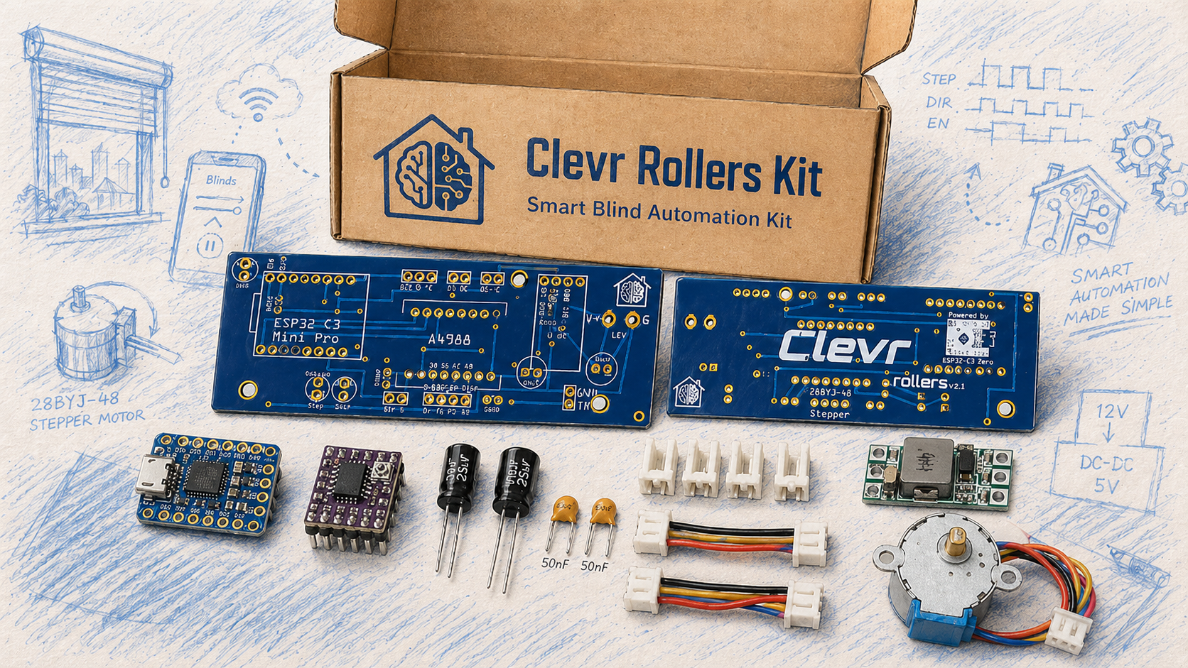
A4988 Driver Module
The A4988 is a complete microstep motor driver with built-in converter for easy operation. The product operates bipolar stepper motors in full, half, 1/4, 1/8 and 1/16 step modes with output drive performance up to 35 V and ±1 A. The A4988 includes a fixed off-time current regulator that operates in slow or mixed attenuation mode. The converter is the key to the ease of implementation of the A4988. Simply input a pulse into the "step" input to drive the motor to generate a microstep. No phase sequence table, high frequency control line or complex interface programming is required. The A4988 interface is ideal for applications where complex microprocessors are not available or overloaded.
The chopping control in the A4988 automatically selects the current decay mode (slow or mixed) during microstep operation. In mixed decay mode, the device is initially set to decay quickly during a partial fixed downtime and then slowly decay during the remaining downtime. Hybrid attenuation current control schemes reduce audible motor noise, increase step accuracy, and reduce power consumption. An internal synchronous rectification control circuit is provided to improve power consumption during pulse width modulation (PWM) operation. Internal circuit protection includes: thermal shutdown with hysteresis, undervoltage lockout (UVLO), and cross current protection. No special power sequencing is required.
The A4988 is available in a surface mount QFN package (ES) measuring 5 mm × 5 mm and has a nominal overall package height of 0.90 mm with an exposed heatsink for enhanced heat dissipation. The package is lead (Pb)-free (suffix -T) with a 100% matte tin leadframe.
- Low RDS (on) output
- Automatic current decay mode detection/selection
- Mixed and slow current decay mode
- Low power dissipation synchronous rectification
- Internal UVLO
- Cross current protection
- 3.3 and 5 V compatible logic power supplies
- Thermal shutdown circuit
- Ground short circuit protection
- Load short circuit protection
- Five optional step modes: Full, 1/2, 1/4, 1/8 and 1/16
The A4988 module has 16 pins in total. Each pin is serving a specific purpose.

We'll go over each group of pins to understand what they do and how they work.
The A4988 requires two separate power supplies:

VDD and GND pins supply power to the A4988’s internal logic circuitry. You can connect these to any voltage between 3V and 5.5V.
VMOT and GND pins provide power to the stepper motor itself. Depending on what type of motor you’re using, this voltage can range anywhere from 8V to 35V.
The A4988 driver offers five different options for step resolution: full-step, half-step, quarter-step, eighth-step, and sixteenth-step modes. Each mode divides the steps differently to give you various levels of precision.
The A4988 has three dedicated pins that let you choose which microstep resolution you want: MS1, MS2 and MS3.

By setting different logic levels (HIGH or LOW) on these pins, you can select any of the five available stepping modes:
| MS1 | MS2 | MS3 | Microstep Resolution |
| Low | Low | Low | Full step |
| High | Low | Low | Half step |
| Low | High | Low | Quarter step |
| High | High | Low | Eighth step |
| High | High | High | Sixteenth step |
It’s important to note that these pins have internal pull-down resistors that keep them LOW by default. This means that if you leave these pins unconnected, the motor will automatically operate in full-step mode.
The A4988 has two primary control inputs that manage motor operation: STEP and DIR.

STEP is the main control input for moving the motor. Every time you send a HIGH signal to this pin, the motor moves forward by one step. The frequency of these pulses determines the motor’s rotation speed—faster pulses result in faster rotation.
DIR pin controls which direction the motor spins. When you set this pin to HIGH, the motor rotates clockwise, and when you set it to LOW, the motor rotates counterclockwise. If your project only needs the motor to spin in one direction, you can simply connect this pin directly to VDD or GND.
The A4988 has three input pins that control when and how the driver uses power: EN, RST, and SLP.

EN (Enable) pin enables or disables the A4988 driver. Since this is an active-low pin, pulling it LOW enables the driver, while pulling it HIGH disables the driver. The good news is that this pin is internally pulled LOW by default, which means the driver is enabled if it’s left unconnected. You might want to use this pin if you need an emergency stop button that can quickly shut down the motor for safety.
SLP (Sleep) pin puts the driver into a power-saving sleep mode. Like the EN pin, this is also active-low, meaning when you connect this pin to LOW, the driver goes to sleep and uses very little power. This feature is particularly useful for conserving power when the motor isn’t in use.
RST (Reset) pin is another active-low pin that resets the driver when pulled LOW, causing the motor to return to its starting position. Resetting is useful when you want to make sure the motor starts from the same place every time.
The motor output pins are where you actually connect your stepper motor to the driver.

You’ll typically find two pairs of wires on a bipolar stepper motor. The 1A and 1B pins connect to the first coil of your stepper motor, while the 2A and 2B pins connect to the second coil.
Wiring an A4988 Stepper Motor Driver to an ESP8266 D1 Mini
This is a complete Schematic accesible at .....
The A4988 driver chip has a maximum current rating of 2 A per coil, but in real-world use, the actual current you can deliver depends heavily on how well you can keep the chip cool. Without additional cooling, the A4988 can typically provide around 1 A per coil before it begins to overheat. To safely use higher currents—especially above 1 A—you’ll need to add a heatsink or implement another cooling method.
For this reason, A4988 driver modules often come with a small heatsink included in the package. It’s highly recommended that you install the heatsink before using the driver. When attaching the heatsink, be careful to ensure it doesn’t make contact with any nearby pins or other electronic components on the board.

One way to maximize stepper motor performance is to supply it with a higher voltage than it’s officially rated for. In particular, using a higher voltage generally allows for higher step rates and increased stepping torque.
Let’s take an example to understand this better. Suppose you’re using a stepper motor that has a maximum current rating of 1 A and a coil resistance of 5 Ω. This indicates a maximum motor supply of 5 V (1 A × 5 Ω = 5 V). Using such a motor with 12 V would allow higher step rates, but the problem is, if you just connect 12 V directly, the motor will try to pull too much current—well beyond the safe 1 A limit. When this happens, the coils inside the motor can overheat, which can permanently damage the motor.
In order to safely use a voltage higher than the motor’s rated voltage, you need to limit the current flowing through the motor’s coils. That’s exactly why the A4988 stepper motor driver includes a small current limit potentiometer. This allows you to set the maximum current that flows through the motor’s coils.

By adjusting the potentiometer properly, you make sure the motor never draws more current than it can safely handle, which helps prevent overheating and keeps your motor safe.