ESP32-DevKitC core board ESP32 development board ESP32-WROOM-32D ESP32-WROOM-32U WIFI+Bluetooth-compatible IoT NodeMCU-32
ESP32-DevKitC V4 with ESP32-WROOM-32 module soldered
|
Key Component |
Description |
|
ESP32-WROOM-32 |
A module with ESP32 at its core. For more information, see ESP32-WROOM-32 Datasheet. |
|
EN |
Reset button. |
|
Boot |
Download button. Holding down Boot and then pressing EN initiates Firmware Download mode for downloading firmware through the serial port. |
|
USB-to-UART Bridge |
Single USB-UART bridge chip provides transfer rates of up to 3 Mbps. |
|
Micro USB Port |
USB interface. Power supply for the board as well as the communication interface between a computer and the ESP32-WROOM-32 module. |
|
5V Power On LED |
Turns on when the USB or an external 5V power supply is connected to the board. For details see the schematics in Related Documents. |
|
I/O |
Most of the pins on the ESP module are broken out to the pin headers on the board. You can program ESP32 to enable multiple functions such as PWM, ADC, DAC, I2C, I2S, SPI, etc. |
Power Supply Options
There are three mutually exclusive ways to provide power to the board:
-
Micro USB port, default power supply
-
5V and GND header pins
-
3V3 and GND header pins
Warning
The power supply must be provided using one and only one of the options above, otherwise the board and/or the power supply source can be damaged.
Header Block
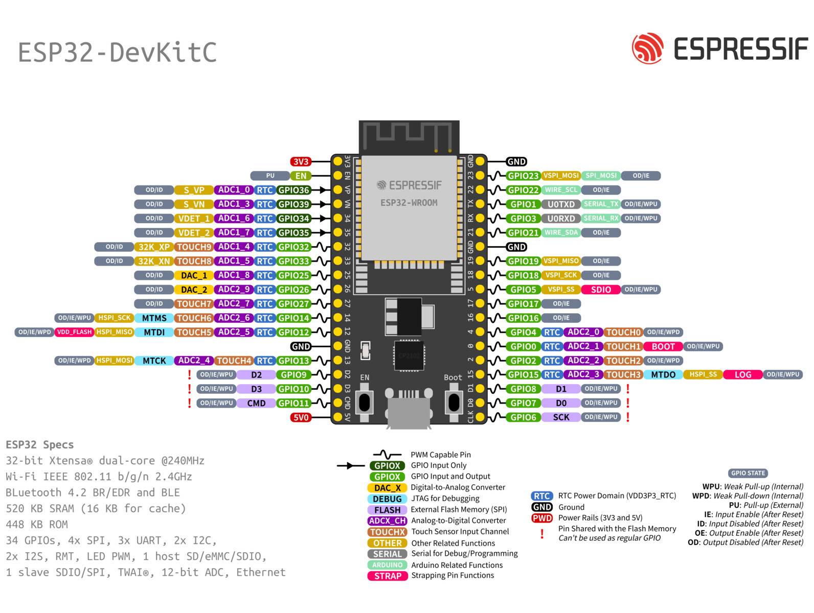
The two tables below provide the Name and Function of I/O header pins on both sides of the board
|
No. |
Name |
Type 1 |
Function |
|
1 |
3V3 |
P |
3.3 V power supply |
|
2 |
EN |
I |
CHIP_PU, Reset |
|
3 |
VP |
I |
GPIO36, ADC1_CH0, S_VP |
|
4 |
VN |
I |
GPIO39, ADC1_CH3, S_VN |
|
5 |
IO34 |
I |
GPIO34, ADC1_CH6, VDET_1 |
|
6 |
IO35 |
I |
GPIO35, ADC1_CH7, VDET_2 |
|
7 |
IO32 |
I/O |
GPIO32, ADC1_CH4, TOUCH_CH9, XTAL_32K_P |
|
8 |
IO33 |
I/O |
GPIO33, ADC1_CH5, TOUCH_CH8, XTAL_32K_N |
|
9 |
IO25 |
I/O |
GPIO25, ADC2_CH8, DAC_1 |
|
10 |
IO26 |
I/O |
GPIO26, ADC2_CH9, DAC_2 |
|
11 |
IO27 |
I/O |
GPIO27, ADC2_CH7, TOUCH_CH7 |
|
12 |
IO14 |
I/O |
GPIO14, ADC2_CH6, TOUCH_CH6, MTMS |
|
13 |
IO12 |
I/O |
GPIO12, ADC2_CH5, TOUCH_CH5, MTDI |
|
14 |
GND |
G |
Ground |
|
15 |
IO13 |
I/O |
GPIO13, ADC2_CH4, TOUCH_CH4, MTCK |
|
16 |
D2 |
I/O |
GPIO9, D2 2 |
|
17 |
D3 |
I/O |
GPIO10, D3 2 |
|
18 |
CMD |
I/O |
GPIO11, CMD 2 |
|
19 |
5V |
P |
5 V power supply |
J3
|
No. |
Name |
Type 1 |
Function |
|
1 |
GND |
G |
Ground |
|
2 |
IO23 |
I/O |
GPIO23 |
|
3 |
IO22 |
I/O |
GPIO22 |
|
4 |
TX |
I/O |
GPIO1, U0TXD |
|
5 |
RX |
I/O |
GPIO3, U0RXD |
|
6 |
IO21 |
I/O |
GPIO21 |
|
7 |
GND |
G |
Ground |
|
8 |
IO19 |
I/O |
GPIO19 |
|
9 |
IO18 |
I/O |
GPIO18 |
|
10 |
IO5 |
I/O |
GPIO5 |
|
11 |
IO17 |
I/O |
GPIO17 3 |
|
12 |
IO16 |
I/O |
GPIO16 3 |
|
13 |
IO4 |
I/O |
GPIO4, ADC2_CH0, TOUCH_CH0 |
|
14 |
IO0 |
I/O |
GPIO0, ADC2_CH1, TOUCH_CH1, Boot |
|
15 |
IO2 |
I/O |
GPIO2, ADC2_CH2, TOUCH_CH2 |
|
16 |
IO15 |
I/O |
GPIO15, ADC2_CH3, TOUCH_CH3, MTDO |
|
17 |
D1 |
I/O |
GPIO8, D1 2 |
|
18 |
D0 |
I/O |
GPIO7, D0 2 |
|
19 |
CLK |
I/O |
GPIO6, CLK 2 |
The pins D0, D1, D2, D3, CMD and CLK are used internally for communication between ESP32 and SPI flash memory. They are grouped on both sides near the USB connector. Avoid using these pins, as it may disrupt access to the SPI flash memory/SPI RAM.