ESP-M1 ESP8285 ESP8266 1M Flash Chip Wifi Wireless Module Serial Port Ultra Transmission With External Antenna Interface
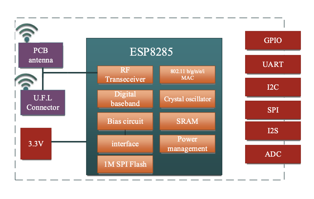
The core processor of the M1/M2 module uses the cost-effective ESP8285 chip. This chip integrates an enhanced version of Tensilica's L106 Diamond series 32-bit core processor in a smaller package, along with on-chip SRAM.
The ESP8285 has complete Wi-Fi network functionality. It can be used independently or as a slave device. It can run on other host MCUs. When the ESP8285 is hosting an application, it can directly start from an external Flash. The built-in high-speed buffer memory is beneficial for improving system performance and optimizing the storage system.
In addition, the ESP8285 can be used as a Wi-Fi adapter through the SPI/SDIO interface or I2C/UART port, and can be applied to any design based on any microcontroller.
SOC characteristics
- Built-in lensilica L106 ultra-low power 32-bit microprocessor, with main frequency support of 80MHz and 160MHz, and supporting RTOS
- Built-in TCP/IP protocol stack
- Built-in 1-channel 10-bit high-precision ADC
- Peripheral interfaces: HSPI, UART, 12C, 12S, IR Remote Control, PWM, GPIO
- Deep sleep maintains a current of 10 uA, while the off current is less than 5 uA.
- Wake up, connect and transfer data packets within 2 milliseconds.
- Standby mode consumes less than 1.0mW of power (DTIM3)
- Built-in 1M byte SPI Flash
Wi-Fi Feature
Supports 802.11 b/g/n/e/i
Support Station, SoftAP, SoftAP + STA Mode
Support Wi-Fi Direct (P2P)
Support hardware acceleration for ССМР (СВС-МАС, Counter Mode), TKIP (Message Integrity Check, RC4), WAPI (SMS4), WEP (RC4), and CRC.
P2P discovery, P2P GO mode/GC mode and P2P power management
WPA/PA2 PSK and WPS
802.11 i Security Features: Pre-Authentication and TSN
Seamless roaming support
Support remote upgrade via AT and cloud-based OTA upgrade
Module peripherals
- 2XUART
- 1XADC
- 1xEn
- 1x Wake-up pin
- 1XHSPI
- 1x12C
- 1x12S
- At most 10x GPIOS
Operating temperature range:
-40°C - 125°C
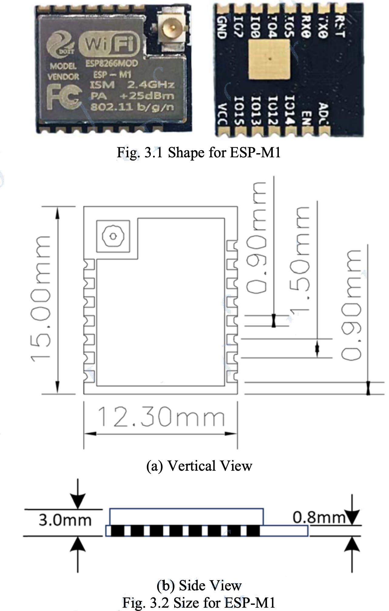
Module size:
12.3mm × 15mm (version M1)
12.3mm × 20mm (version M2)
Application scenario
- Household appliances
- Family automation
- Smart sockets, smart lights,
- Mesh network
- Baby monitor
- Ip camera
- Sensor networks
- Wearable electronic products
- Security ID tag
- Wireless location sensing
- Wireless positioning system beacon
- Industrial wireless control
Module Type
| Name | Antenna Type |
|---|---|
| ESP-M1 | IPEX external antenna |
| ESP-M2 | PCB on board antenna |
Module structure diagram
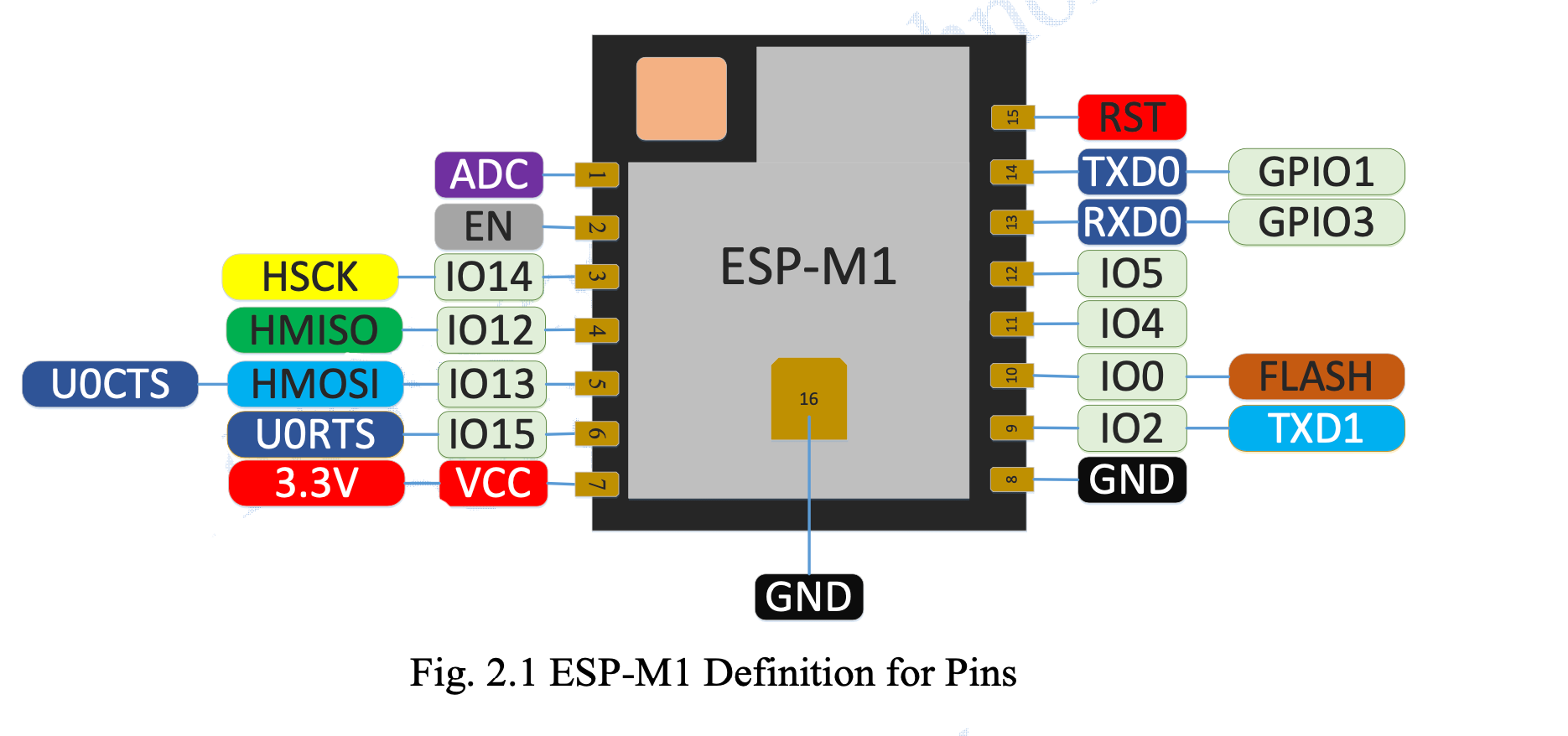
Module pin definition
Selection of Working Mode
Working mode and definition of pins:
| Mode | GPIO15(connected registance) | GPIO0 | GPIO1 |
|---|---|---|---|
| UART download | low | low | high |
| Flash Boot mode | low | high | high |
Shape and size
Shape and size for this module can be shown as follows.
Minimum System
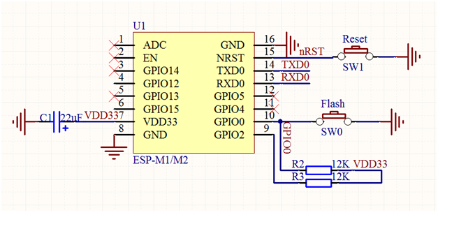
Minimum for ESP-M
- the working voltage for module is DC 3.3V;
- the max current from IO of this module is 12mA;
- RST Pin is enabled when it is low level; and EN pin is enabled when it is high level;
- WiFi module is at update mode: GPIO0 is low level, then module reset to power; Wi-Fi module is at working mode: GPIO0 is at high level, and then reset to power;
- Wi-Fi module is connected to RXD of the other MCU, and TXD is connected to RXD of the other MCU.